
Sun Path and Sun Positions
Sun Position and Horizontal Coordinate System
To maximize energy harvesting, a solar panel must be oriented correctly, facing the sunlight; and this requires knowing the sun positions for each instant in a day and each day in a year in order to construct the sun path for a geographic location.
- Sun path is the most important information ever needed when dealing with solar energy, not only to set panel orientation but also for planning and to determine the production capacity of a site. Sun path is the apparent trajectory perceived by a terrestrial observer; it is specific to a geographic location and it varies from one day to another. The sun path for a full year is made of sun path of each day of the year and the sun path for a given day is made of all the points representing sun positions during the day.
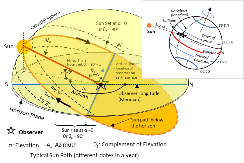
- Sun position is given in the "Horizontal Coordinate" System and the coordinates are defined as "Sun Azimuth" and "Sun Elevation".
Horizontal Coordinate System
It is one of many astronomical coordinate systems used to indicate the location of celestial objects relative to a terrestrial observer.
Horizontal Coordinate System is based on an imaginary celestial sphere, centered at observer geographic location; the position of a celestial object is fully defined by three elements:
- Observer geographic Position: this is the latitude and the longitude;
- Time in Calendar Date & Time (regional rules may be applicable to time and time zones); using solar time allows generalization and may be converted to local when needed.
- Position of the Celestial Object is the actual coordinates, given by two angles, Azimuth and Elevation.
- Azimuth: angle in horizontal plane, positive in clockwise direction from north to the position of the sun.
- Elevation: angle from the horizon line upward to the position of the sun. Elevation is zero at sun rise and at sun set; it is maximum at noon (Sun at Zenith).
Illustrating "the Horizontal Coordinate" system
Notes
About Zenith:
Zenith: when describing sun position (i.e. "sun is at the zenith") the sens is that the sun is at its highest elevation, not necessary directly over your head. Saying that the sun is directly over your head, means elevation is 90 degrees which can happen only at the equator and latitude between the tropics.
About noon
Noon is the daytime when the clock is 12:00
- When referring to "solar time", Solar Noon is when the solar time indicates 12:00; it is exactly midway between sun rise and sun set; it is the time when the sun crosses the local meridian (south-north line). Depending on your latitude and the season, the sun will cross your local meridian at the south, at the north or straight over your head.
- Because local time is often referenced to a different meridian than the local, local and solar times are offset from each other by few minutes to few hours, depending on the time zone and angle difference between local meridian and the meridian that dictates the time in the zone.
- Points on the same meridian have the same solar time but may have different local time depending on applicable local juridiction.
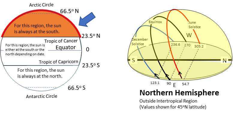
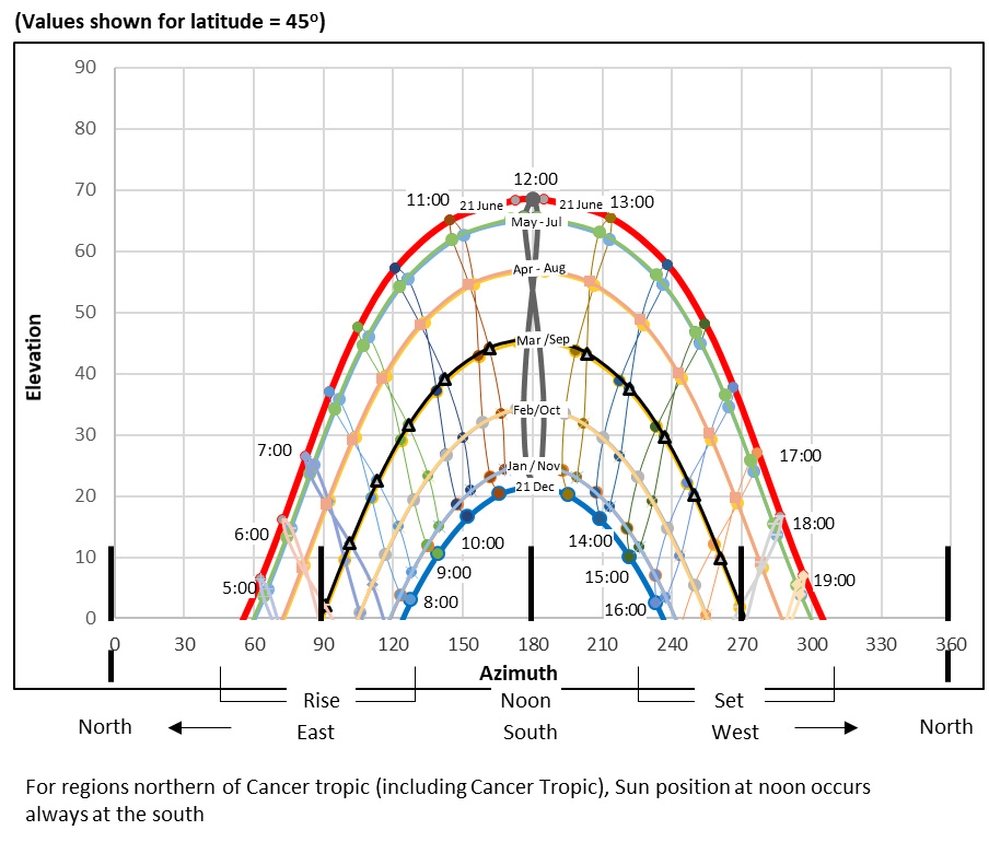
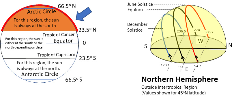
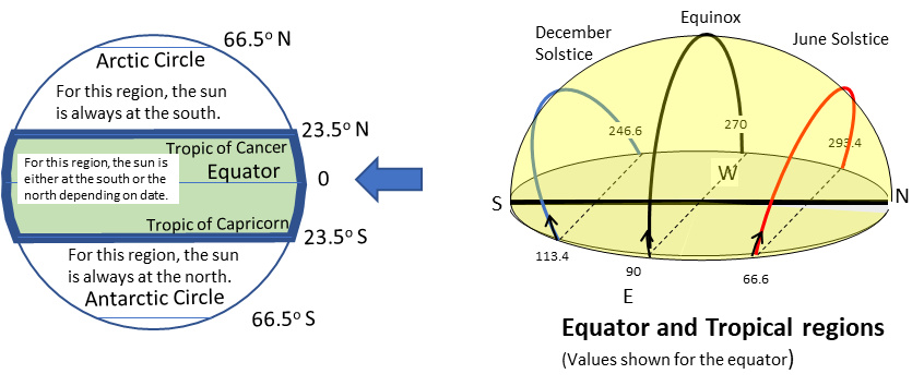
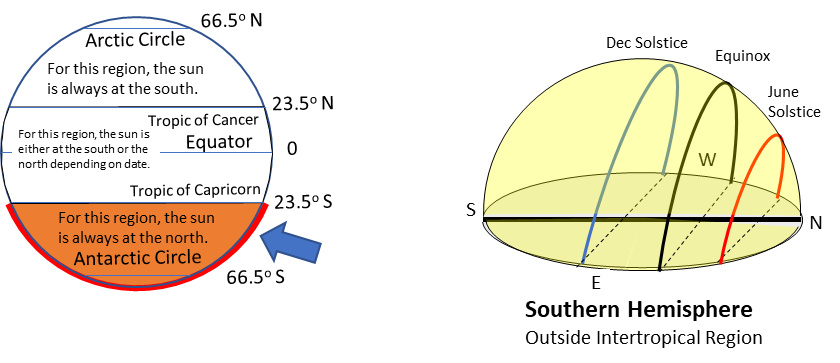
Sun positions relative to latitudes
- Sun is always at the south for latitudes at and north of tropic of Cancer.
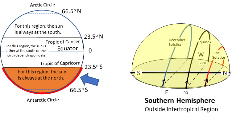
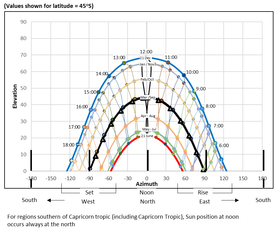
- Sun is always at the north for latitudes at and south of tropic of Capricorn.
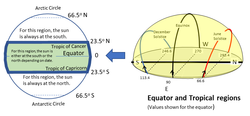
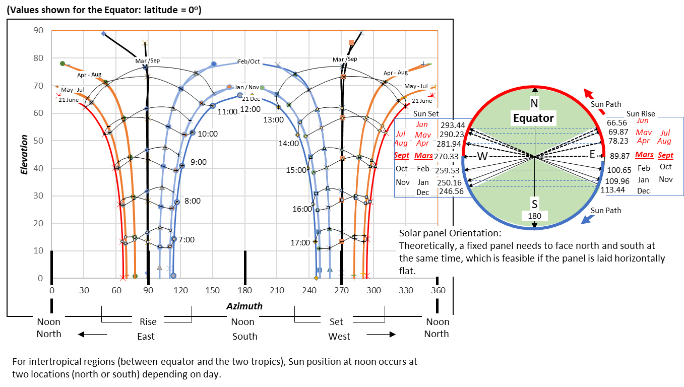
- For the equator and latitudes between the tropics, sun is either south or north depending on period of the year.
Time Zones
- Earth movements are complex, have various "pseudo-periodicity"; earth orbit and orbit eccentricity are essentially affected by other galactic objects. Earth rotation and axis of inclination are mainly affected by precession and nutation resulting in the axis pointing to different direction over centuries and millenniums...
- Solar system and Earth's movements relative to the sun are modeled in algorithms. Calendar date and time, observer's geographic location (latitude and longitude) are variables used by the algorithms to compute the sun position (Azimuth,Elevation);
- Sun position can be computed with good accuracy for any geographic location; no need guessing, no need for trial and error.
- But handling of time reference and time zones is somehow challenging; solar time is naturally convenient for most algorithms, but should be converted to the local time zone.
Useful times in a day:
- Sun rise time (Hour angle at sun rise)
- Noon
- Sun set time (Hour angle at sun set)
Hour angle is zero at noon, negative before noon and positive after noon; it can be expressed in angle or hours, by considering that 24 hours = 360 degrees.
To find the time at sun rise or sun set, is equivalent to finding "Hour angle" when elevation is zero.
After calculating either Sun rise or sun set time, we can easily obtain the total insolation duration in a day; because rise and set time are symmetrical to noon.
Knowing that shadows is shortest at noon has been used in ancient times to determine local noon in major cities.
The tip of the shadow of a vertical structure traces a circular path was also used to determine local noon as well as north-south direction; this method might well be used for the alignment of Egypt Pyramids; for more details, read about "gnomon".
Plotting Sun path
- For this document to be global, we have avoided referencing to standard time and time reference used world wide; we prefer to use solar time which can be converted to applicable local time where necessary.
- When producing sun positions for a day, a spacing of an hour between points is adequate.
- While there are variations from one day to another, we consider that for all practical purpose, a whole month can be represented by any day in the month; preferred date is the 21st of the month.
- By plotting the sun positions from a fixed location, at the same hour each day, you will obtain a pattern shaped as an “8”; it is called an “analemma”.
Solar Panel Orientation
(Equations relating sun position with ideal orientation)
Ideal orientation State
When a solar panel is in ideal orientation state, 100% of incident power acts on the panel and orientation effectiveness is at its maximum.
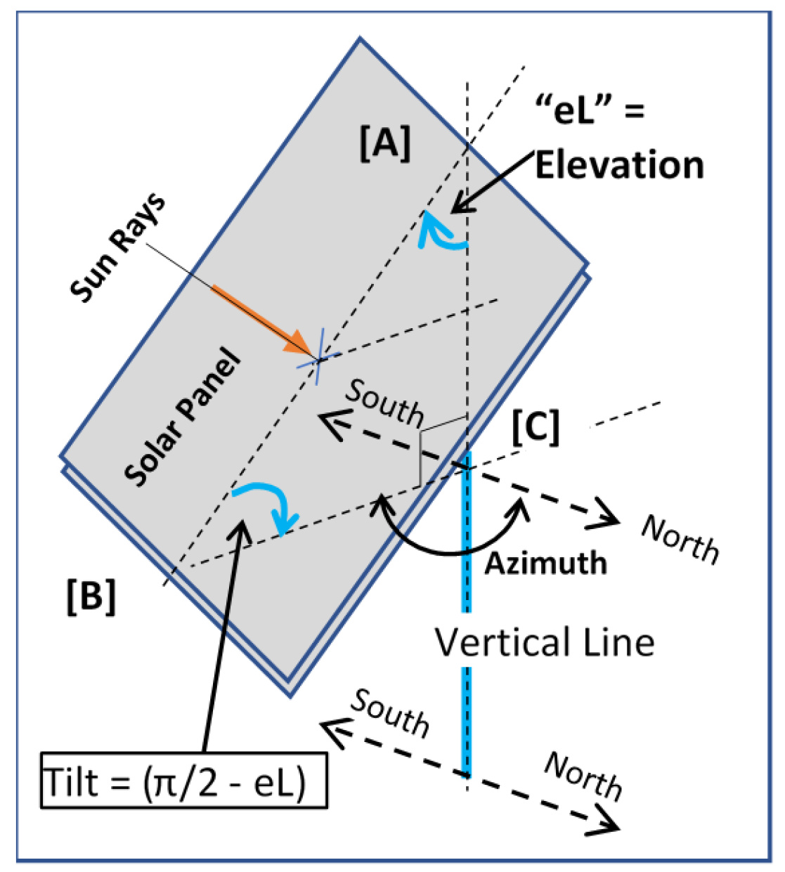
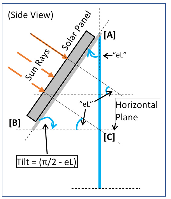
Ideal orientation state is shown in the figure; it is the condition when the surface is perpendicular to the sun rays; from geometric analysis, we can write:
- The panel faces the direction indicated by the azimuth:
ideal_Panel_Azimuth(t) = Solar_Azimuth(t)
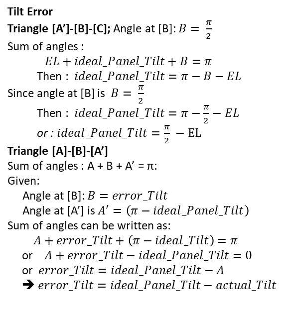
- Solving for angles in the triangle "ABC" yields:
Tilt = 90 - Elevation.
ideal_Panel_Tilt(t) = 90 - Sun_Elevation(t)
Orientation error may occurs in one or both directions.
Orientation Error
(Equations relating orientation errors with ideal orientation)
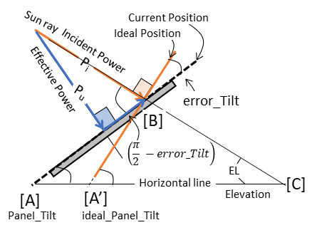
Error in elevation direction -- tilt error
Error relative to ideal tilt is derived from the following figure:
Error in the Azimuth direction
It is derived similarly to above.
Instantaneous orientation error can then be expressed as:
error_Tilt(t) = ideal_Panel_Tilt(t) - actual_Tilt.
error_Az(t) = ideal_Panel_Az(t) - actual_Az.
Whether orientation is fixed, single axis or dual axis tracking, we can calculate orientation error as a function of time and use the result to obtain the production capacity of an installation
Panel Output Power
(function of panel efficiency and orientation error)
The purpose of this section is to find mathematical formulation of effective panel output power as function of orientation error.
Orientation Error on one direction
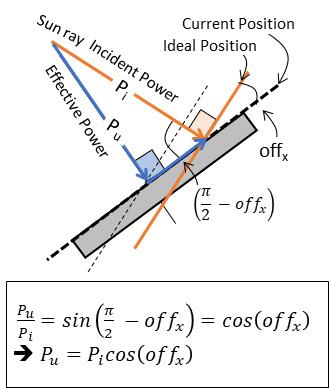
(Find the formula for calculation the usable output power as function of orientation error "offx")
This figure illustrates the case of orientation error relative to either of the angles (one direction at a time)
The orientation error (offx) shown in the illustration, the incident power vector (Pi) decomposes into two components:
- a component that is not usable for power production is parallel to the panel surface.
- the component (Pu) that is effectively usable for power production is perpendicular to surface of the panel.
Orientation Error in both directions
Given errors in both orientation are:
- error_Azimuth(t) = "offAZ,
- error_Tilt(t) = "offEl".
The usable power resulting from error in a direction becomes the incident power for the other direction and we can write:
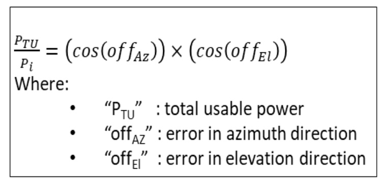
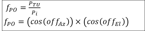
Panel Orientation Factor
Let's define Panel Orientation Factor as:
Panel output power
(note that time is intentionally omitted)

Apply integral function to the equation to find energy.
Variables in the equation are not necessary constant and may be function of time. Note that in this case, integral function is easily carried out in discrete form.
We have considered only the power produced from direct irradiation so far, as this is the dominant component in large power installations Total result also includes indirect component, comprising reflected and diffuse irradiation .
There are cases where only the indirect irradiance is available, often in urban streets where trees and buildings constitute obstructions; obviously, such systems are small and low power and will become out of service should there be few days without sufficient sunlight.
To improve the Panel Output Power
Let's repeat the output equation for convenience:
It is theoretically possible to maintain the ideal orientation state at all time, either by using a real-time tracking system or by playing back a set of pre-calculated angles.
But in a real world, ideal orientation state is practically not maintainable all the time; there is always some orientation error, whether tracking is used or not.
According to the equation, there are only two principal factors that can be acted on to improve the output power:
- Use panel with better efficiency (ƞP)
- Minimize the Orientation Error
Use panel with better efficiency (ƞP)
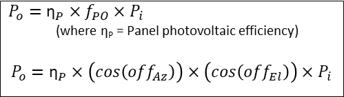
Minimize the Orientation Error
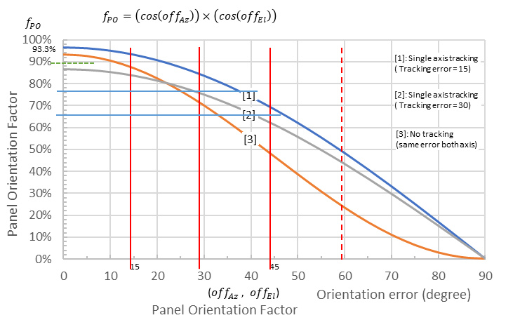
The effect of the orientation error is represented by the second term of the equation, "Panel Orientation Factor":
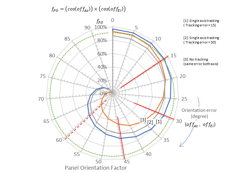
fPO = (cos(offAz))×(cos(offEl))
Minimizing orientation error results in maximizing "Panel Orientation Factor". For all practical purposes, three cases cover all possible situations:
- Dual axis tracking: For more realism, assume 15 degrees constant tracking error for each direction; usable power is then better than 93.3% of incident power. The error is assumed to have been accumulated during consecutive orientation adjustment; hourly update is assumed in this example. (see note).
- Single axis tracking: curves "1" and "2" have respectively 15 and 30 degrees tracking error. If error in the direction not being tracks remains within ±45 degrees, curve "1" will achieve better than 70 of the incident power (60% for curve "2") . Which axis is best to track between azimuth and elevation; what value should we set for the fixed axis; answers depend on the latitude and application constraints.
- Non tracking (curve "3"): with errors less than ±15 degrees, we can capture better than 90 % of the incident power over a period approximately 2 hours. When errors are less than ±45 degree, can can capture better than 50% of the incident power over a period approximately 6 hours (±3). The angle to be used in fixed orientation depends on the latitude; it is calculated further in this presentation.
Note: Fixed orientation angles may be optimized for a full year or a period in the year; it may also be manually adjustable from season to season;
Conversion from angle to time, approximates 15 degrees to an hour based on 24 hours for earth rotation to complete 360 degrees.
Panel Orientation Factor
Table & Curves
Table of Panel Orientation Factor (fPO ) | |||||
Dual Axis Tracking | Track. err.= | 15 | fPO = | 0.93 | |
Error Angle | Single axis tracking | No tracking | |||
Track. err.= | 15 | Track. err.= | 30 | ||
Curve (*1) | Curve (*2) | Curve (*3) | |||
0 | 96.59% | 86.60% | 93.30% | ||
5 | 96.23% | 86.27% | 92.59% | ||
10 | 95.13% | 85.29% | 90.49% | ||
15 | 93.30% | 83.65% | 87.05% | ||
20 | 90.77% | 81.38% | 82.39% | ||
25 | 87.54% | 78.49% | 76.64% | ||
30 | 83.65% | 75.00% | 69.98% | ||
35 | 79.12% | 70.94% | 62.61% | ||
40 | 73.99% | 66.34% | 54.75% | ||
45 | 68.30% | 61.24% | 46.65% | ||
50 | 62.09% | 55.67% | 38.55% | ||
55 | 55.40% | 49.67% | 30.70% | ||
60 | 48.30% | 43.30% | 23.33% | ||
65 | 40.82% | 36.60% | 16.66% | ||
70 | 33.04% | 29.62% | 10.91% | ||
75 | 25.00% | 22.41% | 6.25% | ||
80 | 16.77% | 15.04% | 2.81% | ||
85 | 8.42% | 7.55% | 0.71% | ||
90 | 0.00% | 0.00% | 0.00% | ||
- for dual axis tracking
we assume fPO = 0.933 = (cos(15))×(cos(15))
- (*1) Single axis (tracking error = 15o):
fPO = 0.966×(cos(x))
- (*2) Single axis (tracking error = 30o) :
fPO = 0.866×(cos(x))
- (*3) for non tracking:
we assume OffAz = OffEl
fPO = (cos(offAz))×(cos(offEl))
Solar panel output power is a cosine function of the orientation error; and because of the properties of a cosine function, solar panel is usable over a large range of orientation error.
How much error is acceptable and whether tracking is needed or not depends on what is most important and what constraints are most critical for the application. Tracking comes at additional cost and periodic maintenance.
Various approaches coping with orientation errors
Not long ago, solar panels are costly enough to justify the expense of a tracking system to gain a little bit more of production capability.
Nowadays, prices have dropped so much that, the most cost effective solution to all kinds of inefficiencies and imperfections is to compensate the lost production capacity by installing more power capacity, meaning more panels. With such trend, actual technical problem is not addressed, improvement is not made and we encourage cheap and poor efficiency panels to flood the marketplace.
Examples -- how to compensate for loss of production to meet specified target:
- If panels have poor conversion efficiency, installing higher power panels or more panels compensate for poor efficiency.
- If orientation is poor, we compensate by installing higher power panels or more panels.
- If a site does not have sufficient sun-hours, installing higher power panels or more panels can compensate for required daily production.
- In a site where groups of panels have different orientations, power is not produced at the same time by all the groups; a day may be subdivided into periods; this approach is common in residential installations when roof has multiple inclinations.
These are cases solar panels are deployed despite knowing that the orientation will be imperfect or extremely poor:
- When mounting solar panel in a fixed position on existing structure like a roof or a wall, likely, the orientation will not be perfect; maximum error can be estimated to calculate how much power is effectively produced relative to a ideal orientation.
- There are cases where it is not possible to receive direct sun rays; we then rely on indirect sun rays or diffuse light; this is often the case in urban area where buildings and or trees will obstruct an installation.
- Some deployments are mounted on mobile structure so they can be easily moved around from place to place; examples are mobile street signs and signs used in road construction zones.
- For large power production such as solar farms, special structures are built for installation. For fixed non tracking installations, orientation is set with best effort to achieve some production goal target a specific period of the day or a period of a year.
Fixed Orientation
Calculating fixed orientation:
We have established that for improved power production, we need to minimize orientation errors over a period of time.
A simple solution is to calculate the panel orientation based on averaging the values of sun azimuth and elevations over a period of interest; the period can be a full year or part of a year such as seasons.
- Define a period of interest; Orientation must be periodically adjusted if period of interest chosen is shorter than a year.
- Calculate the average of elevations at noon over the given period;
- With the average above, assume the sun is at that elevation for the whole period, then calculate an hypothetic ideal tilt as:
Fixed_tilt = 90 - Average_Elevation
Tilt versus Latitude
Tilt versus latitude -- Table
| Latitude | Elevation at Zenith | Tilt for a year | ||
| Lowest | Highest | Average in a year | ||
| 0 | 66.5 | 90.00 | 78.25 | 11.75 |
| 5 | 61.5 | 89.99 | 75.75 | 14.26 |
| 10 | 56.5 | 89.99 | 73.25 | 16.76 |
| 15 | 51.5 | 89.93 | 70.72 | 19.28 |
| 20 | 46.5 | 89.97 | 68.24 | 21.77 |
| 23.5 | 43.0 | 90.00 | 66.50 | 23.50 |
| 25 | 41.5 | 88.50 | 65.00 | 25.00 |
| 30 | 36.5 | 83.50 | 60.00 | 30.00 |
| 35 | 31.5 | 78.50 | 55.00 | 35.00 |
| 40 | 26.5 | 73.50 | 50.00 | 40.00 |
| 45 | 21.5 | 68.50 | 45.00 | 45.00 |
| 50 | 16.5 | 63.50 | 40.00 | 50.00 |
| 55 | 11.5 | 58.50 | 35.00 | 55.00 |
| 60 | 6.5 | 53.50 | 30.00 | 60.00 |
| 65 | 1.5 | 48.50 | 25.00 | 65.00 |
| 66.5 | 0.0 | 47.00 | 23.50 | 66.50 |
| 70 | -3.5 | 43.50 | 20.00 | 70.00 |
| 75 | -8.5 | 38.50 | 15.00 | 75.00 |
| 80 | -13.5 | 33.50 | 10.00 | 80.00 |
| 85 | -18.5 | 28.50 | 5.00 | 85.00 |
| 90 | -23.5 | 23.50 | 0.00 | 90.00 |
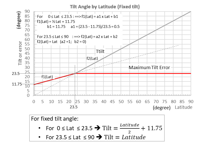
For latitudes between 23.5 and 90 degrees, maximum tilt error is 23.5; the error is less at lower latitude. Using 23.5 as maximum tilt error to calculate the usable power shows that better than 75 % of incident power is usable. To obtain better result, we can subdivide the globe into smaller range of latitudes or subdivide a year into multiple periods (2 or 4), in which case, we must manually adjust the orientation for each period.
At the best, we will achieve 88%; is the effort worth 13% more (88-75) . This is the same question we must ask if we consider using single or dual axis tracking.
The curve shows that fixed tilt can be expressed as linear function of latitude.
[C]
To allow for some generalizations, we find it practical to subdivide the globe into regions (five latitude ranges) with some common characteristics and specificity; for instance, in single axis tracking installation, the axis doing the tracking may not be the same for all regions. Tropical region is different than others; contrary to others regions where the sun is always at the south for the northern hemisphere and at the north for the southern hemisphere, the sun will be either at the north or the south dependent on the period in the year.
For all practical purpose, earth can be subdivided into five principal regions, well delimited by the tropic circles, arctic and antarctic circles:
- Arctic region: between the north pole and the arctic circle (part of northern hemisphere)
Arctic circle = 66.5 degree latitude north
Periods of 24 hours daylight in summer and 24 hours darkness in winter.
Periods of 24 hours daylight in summer and 24 hours darkness in winter.
Solar system in this region can only be seasonal.
(See sun path at selected latitudes).
- Medium Northern hemisphere : between the arctic circle and the Tropic of Cancer
Tropic of Cancer = 23.5 degree latitude north.
Sun is always at the south.
(See sun path at selected latitudes).
- Equatorial and Inter-tropical Region:(Region between the tropics)
Tropic of Capricorn = 23.5 degree latitude south.
Sun is either at the south or the north depending on the date and period the year.
Choosing a fixed orientation is not as simple as for the other regions.
(See sun path at selected latitudes).
- Medium Southern hemisphere: between Tropic of Capricorn and antarctic circle
Sun is always at the north.
(See sun path at selected latitudes)
- Antarctic region: between the antarctic circle and the south pole (part of southern hemisphere)
Periods of 24 hours daylight in summer and 24 hours darkness in winter.
Solar system in this region can only be seasonal.
(See sun path at selected latitudes).
Note:
- Latitude defining the tropics = "earth inclination" = 23.5
- Latitude defining the polar circles = "(90 degree) - (earth inclination)" = 90 - 23.5 = 66.5
Need for Tracking or not
Most applications operate without tracking; whether you need it or not, depends on the constraints of your application. The final decision will also depend on total energy production gain versus cost; tracking also comes with extra maintenance cost.
Gain due to tracking
Daily energy production is integral over the day of power by time product. If we divide a day into several small periods, we can also write:
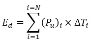
Where
- N = arbitrary number of periods in a day.
- ΔT = time duration of a period
- Pu = usable power during a period
The formula is applicable for tracking as well as non tracking. Orientation error is minimized in each period, in the case of tracking, thus maximizing usable power.
Yearly energy production is obtained by the sum of all daily production:
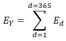
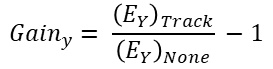
By computing and comparing yearly production for tracking and non tracking, the gain due to tracking is given by:
Comparison
(energy production between tracking and non tracking)
Assumption:
- Let's divide a day into 3 equal periods (period before noon, period at noon and period after noon).
- For non tracking, we assume ±25 error at noon period and ±40 for other period;
- For tracking systems, assume ±15 tracking error.
Results of total daily energy are:
- Non tracking: 66.5%
- Single axis tracking: 82.8%
- dual axis tracking: 93.6%
Cost of tracking
The cost must also include the maintenance cost of the tracking system; the total cost is what we need to compare with the cost of extra panels to compensate for the lost of production.
Note that in mini grids and large grid-tied solar farms, may be justified to opt for tracking in order to minimize land usage.
Consideration for better results
(Tracking versus non tracking)
There are several things that can be done at the panel level that can help increase production efficiency.
A. Tracking
Tracking can be:
- single axis: where either Azimuth or Elevation only is tracked. The axis that is fixed may be user adjustable
- dual-axis: where both Azimuth and Elevation are tracked;
Adjustment is generally not continuous and not instantaneous; it is rather done in steps and the periodicity is chosen such as the accumulated offset is small. One adjustment per hour is acceptable, because offset being less than 20 degree ensure that 90 % of the incoming sun power can be captured. Four adjustment per hour is more than necessary.
Tracking system consists essentially of three principal functions:
- Sun position detection this includes all the mechanism to find the current sun position and all processing necessary to trigger panel orientation update. Detecting actual sun position may be optional; it can be replaced by playing back a pre-programmed set of data for the specific geographic location; implementing this option will require calendar and real-time clock.
- The other function in tracking system is power electronics, motor(s) and control electronics. The system must be self adjust and positions itself for the beginning of each day.
- Powering the system (power source)
Tracking is costly; it involves maintenance and may not be justifiable for small and modest installations.
B. Non Tracking
(Permanently Fixed Orientation)
Most installations are "Non Tracking" and mounted permanently in a fixed orientation; therefore, panels are exposed to sunlight, for couple of hours per day in the best case and exposure is poor for the rest of the day. Which direction to face the solar panel in order to have the optimum insolation hours per day will depend on the geographic location and the season. By analyzing the sun path, we can choose which direction is most suitable for our geographic location and the period of the day when the power is needed the most.
General observation:
For regions northern the tropic of cancer and southern the tropic of capricorn, the sun is always at the south and the north respectively.
A day can be subdivided in three periods and panel orientation can be set for best result during a period; different panel groups may also be dedicated for each period:
- Before noon.
- Noon period: this is approximately a total of of two hours around noon.
- After noon.
For period of the day around noon, elevation is highest but Azimuth varies by a large amount per hour.
For other periods of the day (before noon and afternoon), it is the elevation that has significant variation per hour.
Orientation may be chosen for period before noon, at noon or after noon; however, it is worth mentioning that, time of exposure to sun rays will be shorter if noon is chosen because the sun position changes more quickly at noon (angles change over large amount, for short period of time).
But this general observation is not sufficient to be the only basis for choosing the orientation, the position of the sun at noon is not the same for every day. The solution is to draw the sun path for every day for the geographic location then select the region of the graph that can be acceptable for our particular application.
We need to choose a setting that allows sufficient power and or energy production per day; which part of the day, the energy is needed the most, is a factor to take in consideration.
It is more likely we end up with better performance at a particular period of the year, at the cost of poorer performance during the rest of the year.
For instance, applications outside the inter-tropical region, may choose to optimize the orientation for winter season at the cost of poor production during other seasons.
The installation may also provide for multiple taps, selectable manually for different seasons.
For better result, we may also consider:
- Periodic adjustment, but it is high maintenance, prone to human error.
- Use panels that have higher conversion efficiency. More efficient panel is much more costly than other simple solution; compensating installation imperfection by better panel only would require efficiency improvement beyond today's technology.
- Increase the installed power capacity by increasing the number of panels or use panels with higher power. This approach is the most cost effective considering the solar panel cost is continuously dropping. The drawback is that more space is required to install more panels or larger panels.
Spacing between panels
(To avoid shadow from others)
Structures, buildings, trees, chimney, ... and other panels can cause obstruction and cast shadow onto the surface of a panel.
For any specific geographic location, there is a specific sun path; by mapping all objects that can potentially cause obstruction or shadow, we will be able to tell where shadow occurs and when.
Formula to calculate Length of the shadow
Panels should be mounted, distant away from objects that may cast shadow; such objects include trees, chimneys, nearby structures and other panels. A formula to calculate the length of the shadow as a function of sun elevation, panel tilt and panel size is established here.

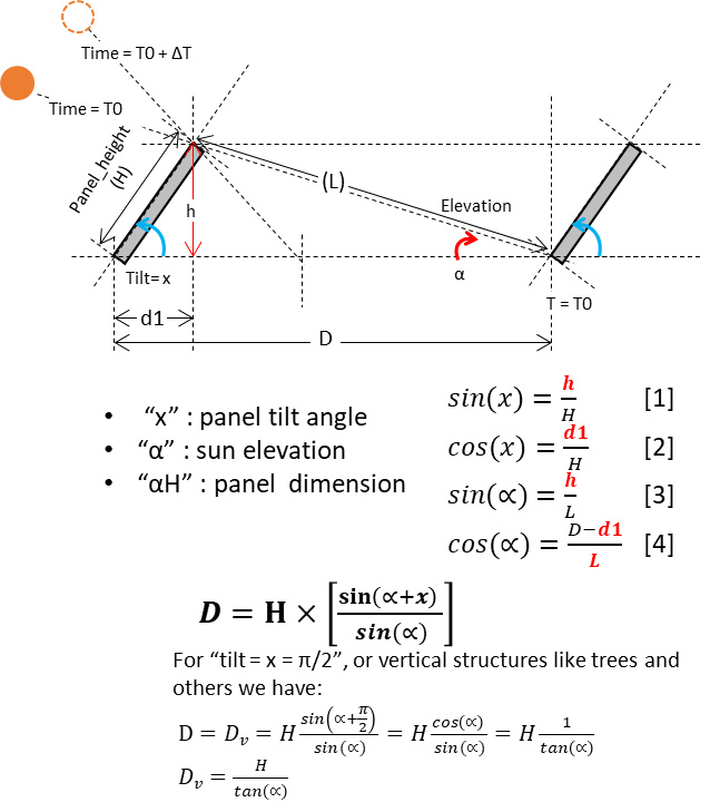
The formula to calculate shadow size is determined to be:
D(x,α) = H sin(x+α)/sin(α) or D(x,α) = H * m(x,α)
where :
x = tilt
α = sun elevation
m(x,α) = [sin(α+x)]/[sin(α)] multiplier function
The formula is also applicable to objects such as trees and building.
The curve of the multiplier function is shown further below.
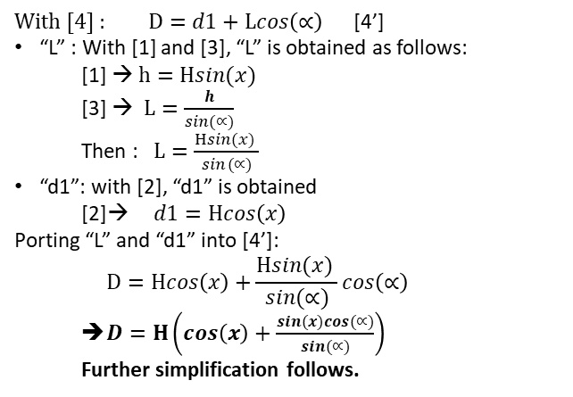
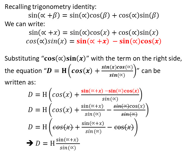
Following is how the formula "D = H x [sin(α+x)]/[sin(α)]" has been obtained:
How much spacing is needed:
The minimum spacing needed is equal to the maximum length of the shadow and this occurs when elevation is minimum, which is at sun rise and sun set. If operation is being planned to start early after sun rise while elevation is low, then, we need larger spacing between panels, hence, bigger land to build the site.
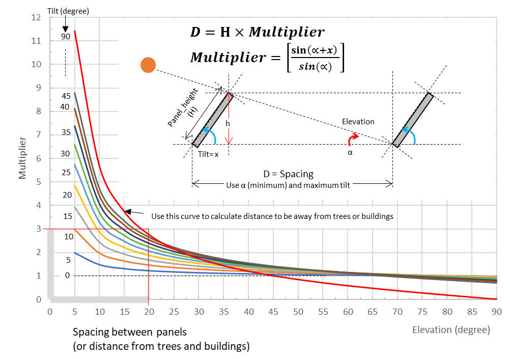
Operating while elevation is below 20 degree may require spacing up to three times the size of the panel.
In locations that are far away from the tropics, larger spacing is required for the periods in the year that the elevation is very low; beyond 55 degree latitude, elevation remains below 20 degree for many months.
Tropical region may delay operation until elevation is sufficiently high and still enjoy a reasonable sun time.
It is true that tilt depends on geographic location; but indirectly; tilt angle depends directly on elevation only;
The tilt angle depends on geographic location. For fixed orientation, it is lower around the equator and between the tropics but larger and larger when further away from the tropics. the minimum operating sun elevation is known.
Not all combinations "x" and "α" make practical sense:
- For geographic locations where the tilt angle is low, which is in the tropical regions, it is possible to delay active operation until sun elevation is sufficiently high
- For locations where the tilt angle is high, which is far away from the tropics, the good option is to start active operation at sun elevation as low as practically possible.
- Start operating from early in the morning, will also end late in the afternoon; larger spacing is required between panels, because shadow is longer when sun elevation is low.
- When operating around noon, elevation is highest and shadow shortest; shorter spacing can be used between panels in this case.
- Installation with tracking mechanism would like to operate over a wide window, including early in the beginning of the day when sun elevation is very low and shadow long; this would require larger separation between the panels.
- Fixed, non tracking installations, operate during limited number of hours in a day anyway; a good choice would be to start operating when sun elevation is not too low, meaning as late as possible so that shadow size is reasonably small and spacing between panels too.
Sun path at the north
Sun paths at the North
| Sunpath_NorthPole.png | 61.1KB | North Pole |
| Sunpath_N85.png | 75.2KB |
| Sunpath_N80.png | 81.4KB |
| Sunpath_N75.png | 90.4KB |
| Sunpath_N70.png | 99.6KB |
| SunPath_ArcticCircle.png | 121.2KB | Arctic Circle |
| Sunpath_N65.png | 108.9KB |
| Sunpath_N60.png | 114.0KB |
| Sunpath_N55.png | 119.6KB |
| Sunpath_N50.png | 66.6KB |
| Sunpath_N45.png | 127.7KB |
| Sunpath_N40.png | 130.9KB |
| Sunpath_N35.png | 132.6KB |
| Sunpath_N30.png | 137.5KB |
| Sunpath_N25.png | 140.1KB |
| SunPath_TropicCancer.png | 171.5KB | Tropic of Cancer |
Sun path at the equator and tropical region
Sun Paths -- Equator and the tropics
| Sunpath_N20.png | 164.8KB |
| Sunpath_N15.png | 164.3KB |
| Sunpath_N10.png | 175.7KB |
| Sunpath_N05.png | 176.0KB |
| Sunpath_Equator.png | 177.5KB | Sun Path at the Equaror |
| Sunpath_S05.png | 178.3KB |
| Sunpath_S10.png | 122.4KB |
| Sunpath_S15.png | 124.9KB |
| Sunpath_S20.png | 126.8KB |
Sun path at the south
Sun Paths at the South
| SunPath_TropicCapricorn.png | 125.4KB | Sun Path at the Tropic of the Capricorn |
| Sunpath_S25.png | 137.3KB |
| Sunpath_S30.png | 135.3KB |
| Sunpath_S35.png | 131.0KB |
| Sunpath_S40.png | 127.7KB |
| Sunpath_S45.png | 124.0KB |
| Sunpath_S50.png | 121.8KB |
| Sunpath_S55.png | 117.7KB |
| Sunpath_S60.png | 113.7KB |
| Sunpath_S65.png | 107.9KB |
| SunPath_AntarcticCircle.png | 106.0KB | Sun Path Antarctic Circle |
| Sunpath_S70.png | 101.3KB |
| Sunpath_S75.png | 93.2KB |
| Sunpath_S80.png | 83.4KB |
| Sunpath_S85.png | 78.6KB |
| Sunpath_SouthPole.png | 66.2KB | Sun path_South Pole |